Project Description
UTT warehouse hall, Biatorbágy, 2016
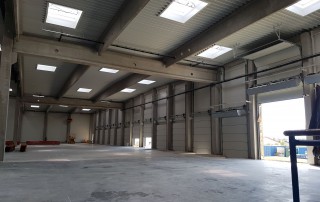
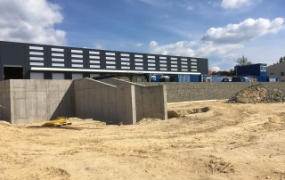
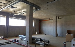
The UTT warehouse hall is a logistic facility of approximately 12,000 sq.m. with monolith and prefabricated reinforced concrete structure. The product development and the design of the monolith structures were carried out by Plan31 Mérnök Kft.
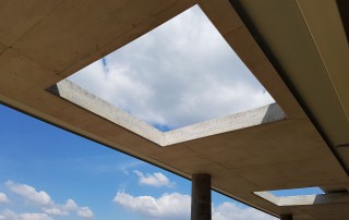
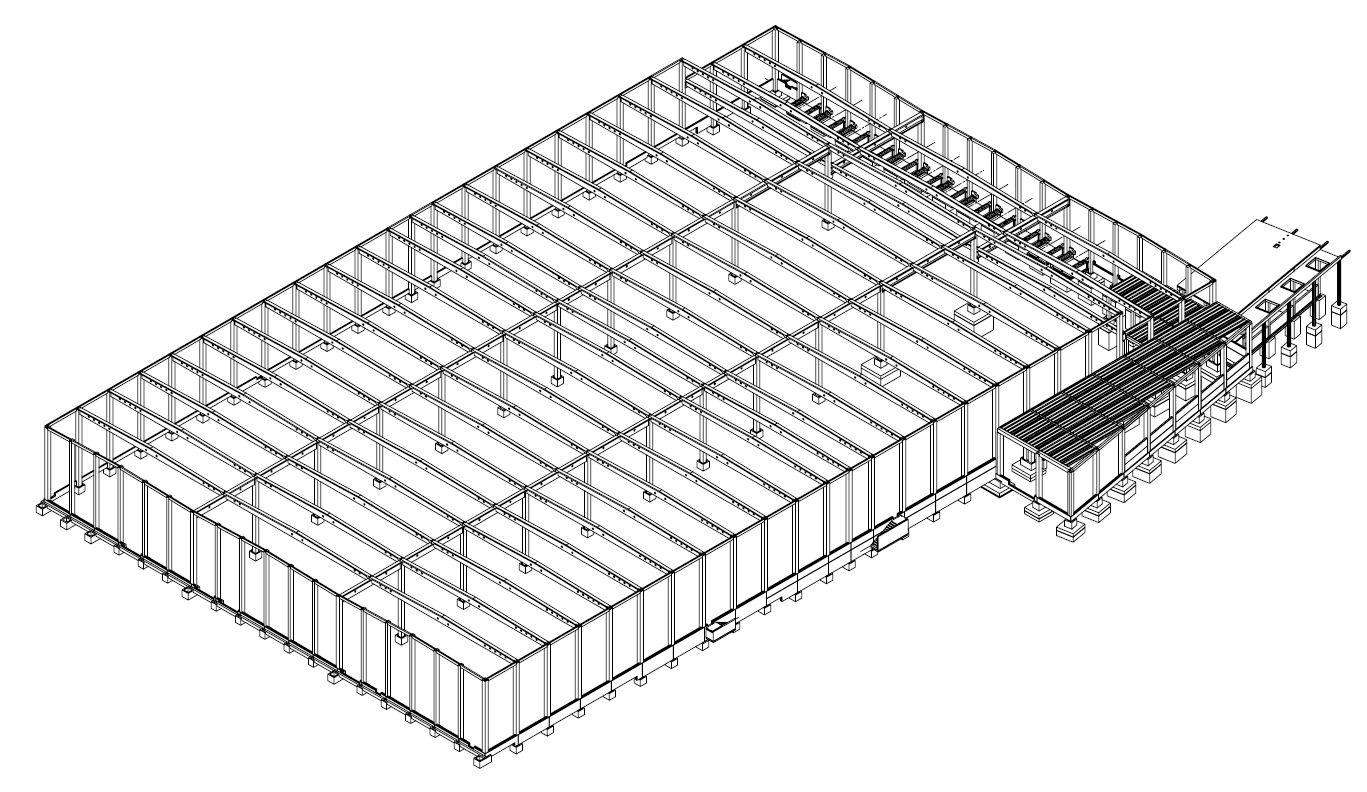
A warehouse hall was built on the steep slope area, consisting of 3 naves; the hall can be extended in the northerly direction. A fork-lift truck charging building and an office/locker-room is connected to the hall through structure duplication thermal expansion. A crosswise grid of the hall is 3 x 28.2 m. The longitudinal grid is 11 x 6 + 2 x 4.35 + 11 x 6 m. Thus the overall dimension of the building layout is 84.60 x 140.70 m measured by grid. The office and locker room building has two floors. The -1 level is at -3.85 m, ground floor is at ±0.00. The height of the attic is + 5.00 m. The longitudinal grid size is 3 x 6 m, built beside the hall and fork-lift truck charger with a trapezoidal layout with a console section, narrowing from approx. 2.58 m. The crosswise grid is 2 x 5.08 m to which the colonnade supporting the projecting roof is connected with a distance of 3.54 m.
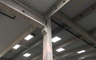
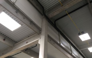
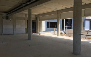
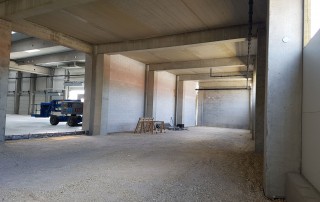
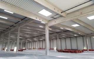
The pillars of the halls, the fork-lift truck charger and the office/locker-room are prefabricated reinforced concrete columns fixed into the basic body. The size of the intermediate pillars of the hall is 70 x 70 cm; the size of the pillars at the outermost line is 60 x 60 cm while the size of the end-wall is 40 x 60 cm. The size of the fork-lift truck charger is 60 x 60 cm. The office/locker-room has 45 x 45 cm pillars on level -1. The ground floor pillars and the pillars supporting the projecting roof are round, with 45 cm diameter. The upper ends of the pillars supporting the roof structure of the hall are forked and the purlins and principal beams sit into these forks. The bottom end of the pillars is saw-toothed, same as the bowls.
Short principal beam reinforced concrete structural skeleton was used in this hall i.e. the principal beams (TP120/50-ITP125/60) were installed on the shorter, 12(18) m line of the 12(18)x28.2 m base grid and the purlins (TS133/50) in the 28.2 m direction, with 6.00 m divisions.
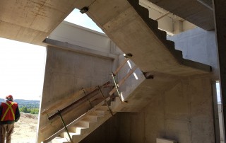
Both floors of the office/locker-room are 20 cm thick reinforced concrete plates resting on transverse beams (with numbered axis direction) with multiple supports; the lower formwork and ironwork is provided by AFB crusted panels with upper ribs. The 3-arm staircase is a monolith reinforced concrete structure.
During the design phase we prepared the 3D model of the complete reinforced concrete shell at first so that we could provide the design/execution partners with it before preparing the product designs. Simultaneously with preparing the model we prepared the statics calculations. Processing started after that; allocation (designation) designs were prepared of the reinforced concrete components – bowls, pillars, intermediate floor, roof beams, pedestal components, docking stations, firewalls, stairs, armatures etc. – and then shuttering and reinforcement plans were prepared.
Axonometry

Common building elements used in the project
Cross-section of pillars

Cross-section of principal beam

Cross-section of perlin

